CN >
CN >
In today's trend of highly integrated and miniaturized electronic products, thermal management has become a major challenge for design engineers. If the heat generated by a product during operation cannot be effectively dissipated, it can lead to performance degradation, equipment failure, or even safety hazards. Among various thermal interface materials, thermal conductive silicone pads play a crucial role in various electronic devices as an efficient heat transfer medium. So, how exactly should you select a silicone pad with the appropriate thermal conductivity based on the product's heat generation? This article will delve into this core question, revealing the secrets of thermal management selection.
Why Does Heat Generation Determine the Selection of Thermal Conductive Silicone Pads?
The heat generated by a product directly dictates the amount of heat that needs to be removed through the thermal path. If the heat conduction capability of the thermal conductive silicone pad (determined by its thermal conductivity) is insufficient to cope with the product's heat generation, heat will accumulate locally, leading to a temperature increase. This is like a canal: the greater the water flow (heat generation), the wider the canal (higher thermal conductivity) needed for smooth drainage.
Core Function of Thermal Conductive Silicone Pads
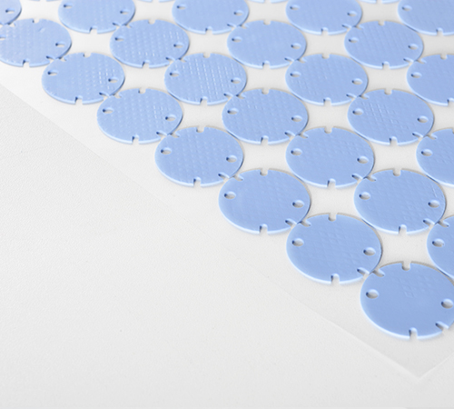
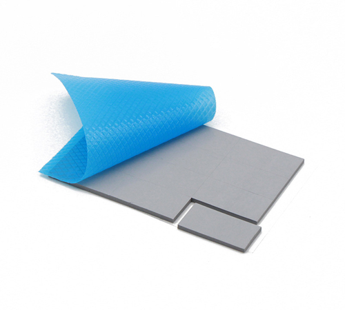
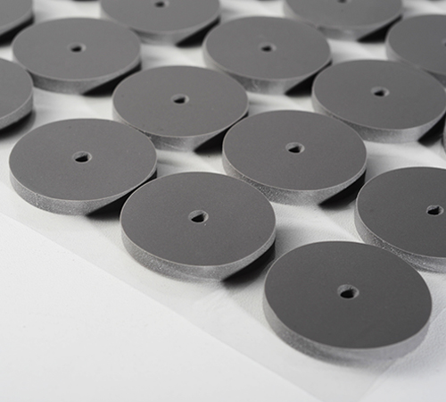
The primary function of thermal conductive silicone pads is to fill the tiny gaps between heat-generating components and heat sinks, reducing contact thermal resistance, thereby establishing an efficient heat transfer path. With their excellent flexibility, insulation, and compressibility, they can closely conform to irregular surfaces, expel air, and quickly transfer heat to the heat sink.
Core Considerations: Product Heat Generation and Thermal Resistance
When selecting a thermal conductive silicone pad, it's not simply a matter of "the higher the thermal conductivity, the better." We need to comprehensively consider the product's heat generation, target operating temperature, heat dissipation space, and the overall thermal resistance budget.
1. Estimating Product Heat Generation (P)
This is the first and most critical step in selection. Heat generation is usually measured in watts (W) and can be obtained or estimated through the following methods:
● Component Data Sheets: Data sheets for core heat-generating components such as chips and processors often provide their maximum power consumption.
● Actual Testing: During the product prototype stage, test the actual heat generation power of components under different operating conditions using tools like thermocouples or infrared thermal imagers.
● System Total Power Consumption Breakdown: For complex systems, it's necessary to estimate and summarize the power consumption of each module.
2. Setting Target Temperature and Temperature Rise (ΔT)
You need to clearly define the maximum allowable temperature for the product under normal operating conditions, as well as the temperature difference between the component junction temperature and the ambient temperature. For example, if the maximum allowable junction temperature of a chip is 100∘C and the ambient temperature is 25∘C, then the maximum allowable temperature rise is 75∘C.
3. Understanding the Concept of Thermal Resistance (Rth)
Thermal resistance is a physical quantity that measures an object's ability to impede heat transfer, with units of ∘C/W. The lower the total thermal resistance, the better the heat dissipation effect. Thermal resistance in the heat transfer process can be divided into:
● Internal Chip Thermal Resistance: The thermal resistance within the chip package.
● Contact Thermal Resistance: The thermal resistance between the component and the thermal material, and between the thermal material and the heat sink.
● Thermal Conductive Silicone Pad's Own Thermal Resistance: Determined by its thickness and thermal conductivity.
● Heat Sink Thermal Resistance: The thermal resistance of the heat sink dissipating heat into the environment.
● Ambient Thermal Resistance: The thermal resistance of the surrounding air.
In thermal management, we usually focus on the total thermal resistance Rtotal from the heat source to the environment. Its relationship with heat generation P and temperature rise ΔT is:
ΔT=P×Rtotal
Therefore, Rtotal=ΔT/P.
How to Calculate the Required Thermal Conductivity Based on Heat Generation?
In practical applications, we can roughly estimate the required thermal conductivity of a thermal conductive silicone pad using the following simplified model.
Step 1: Calculate the Required Total Thermal Resistance (Rtotal)
Based on the product heat generation P and the maximum allowable temperature rise ΔTmax, calculate the maximum total thermal resistance allowed for the system:
Rtotal,max=ΔTmax/P
Step 2: Estimate Other Thermal Resistance Components
In the total thermal resistance, in addition to the thermal resistance of the thermal conductive silicone pad, there are also internal chip thermal resistance, heat sink thermal resistance, contact thermal resistance, etc. Although precise estimation is complex, we can roughly allocate a portion of the thermal resistance to these links.
Rother=Rchip+Rsink+Rcontact_top+Rcontact_bottom
Step 3: Calculate the Maximum Required Thermal Resistance for the Thermal Conductive Silicone Pad (RTIM)
The thermal resistance of the Thermal Interface Material (TIM) should satisfy:
RTIM,max=Rtotal,max−Rother
It is important to note that RTIM,max here refers to the maximum thermal resistance that the thermal conductive silicone pad can provide; in practice, we want it to be as small as possible.
Step 4: Calculate the Minimum Required Thermal Conductivity (λ)
The thermal resistance of the thermal conductive silicone pad is related to its thickness L and thermal conductivity λ and area A by:
RTIM=L/(λ×A)
Therefore,we can derive the minimum required thermal conductivity:
λmin=L/(RTIM,max×A)
Where:
● L: Thickness of the thermal conductive silicone pad (unit: m). Usually selected based on the gap size; thinner is better, but it must ensure complete filling.
● A: Contact area between the thermal conductive silicone pad and the heat source (unit: m2).
Example:
Assume a chip has a heat generation P=15W, a maximum allowable junction temperature Tj=90℃, and an ambient temperature Ta=30℃. The heat sink thermal resistance Rsink=3℃/W (assumed known and includes contact thermal resistance), and the chip package thermal resistance Rchip=1℃/W. The thermal conductive silicone pad thickness L=0.5mm=0.0005m, and the contact area A=20mm×20mm=0.0004m2.
1. Maximum Allowable Temperature Rise: ΔTmax=Tj−Ta=90℃−30℃=60℃
2. Maximum Allowable Total Thermal Resistance: Rtotal,max=60℃/15W=4℃/W
3. Other Thermal Resistances: Rother=Rchip+Rsink=1℃/W+3℃/W=4℃/W
● Note: This example simplifies the calculation; in practice, heat sink thermal resistance usually does not directly include contact thermal resistance and needs to be calculated separately.
4. Required Thermal Resistance for Thermal Conductive Silicone Pad: RTIM,max=Rtotal,max−Rother=4℃/W−4℃/W=0℃W
● Important Note: This result indicates that in this scenario, if the heat sink and chip package thermal resistance already fully utilize the total thermal resistance budget, there is almost zero thermal resistance left for the thermal conductive silicone pad. This means we would need a material with theoretically zero thermal resistance, i.e., extremely high thermal conductivity, or a re-evaluation of the reasonableness of the heat sink and chip thermal resistance.
● Practical Adjustment: In actual selection, we usually leave some margin for the thermal conductive silicone pad. Let's assume we want the thermal conductive silicone pad's thermal resistance contribution to not exceed 0.5℃/W. RTIM,target=0.5℃/W
5. Minimum Required Thermal Conductivity: λmin=L/(RTIM,target×A)=0.0005m/(0.5℃/W×0.0004m2)=0.0005/0.0002=2.5W/(m⋅K)
Therefore, in this case, a thermal conductive silicone pad with a thermal conductivity of at least 2.5W/(m⋅K) or higher should be selected.
Selection Pitfalls and Precautions
● Thermal conductivity is not the only indicator: While thermal conductivity is important, thermal resistance is an even more crucial consideration. Even with very high thermal conductivity, if the silicone pad is too thick or the contact area is too small, its thermal resistance can still be high.
● Thickness selection: The thickness of the thermal conductive silicone pad should be as thin as possible, but ensure it effectively fills the gaps and avoids excessive pressure that could damage components.
● Long-term reliability: Consider the silicone pad's stability at long-term operating temperatures, compression deformation, and whether it will "pump-out."
● Insulation performance: In applications requiring electrical insulation, it is essential to choose a thermal conductive silicone pad with good insulation properties.
● Cost considerations: Silicone pads with higher thermal conductivity typically come at a higher cost. A cost-benefit analysis should be performed while meeting heat dissipation needs.
● Importance of actual testing: Theoretical calculations serve as a guide, but the actual heat dissipation effect of the product still needs to be verified through thermal testing. Conduct thermal imaging and thermocouple tests on prototypes to ensure the effectiveness of the thermal management solution.
Conclusion
Choosing the right thermal conductive silicone pad is a critical component of successful product thermal management. It's not just about "sticking on a piece of silicone," but a systematic engineering process that requires comprehensive consideration of heat generation, temperature targets, thermal resistance distribution, and material characteristics. We hope this article provides you with clear insights and practical guidance for your product thermal management designs.
Have you encountered challenging thermal management issues in your projects? Feel free to share your experiences and let's discuss!